Macro Pad for 3DConnexion SpaceMouse Wireless

Motivation

I was aware of CAD Mice, but always considered them a luxury and resited to urge to purchase one as I couldn't justify the hefty price tag. After using a work colleague’s SpaceMouse Compact, I bit the bullet and purchased an entry-level SpaceMouse Wirelessby by 3dconnexion. I was in love, and it dramatically changed the way I interact with CAD models.

The downside of purchasing a lower-end model was now I have to switch my hand between the SpaceMouse and keyboard to use the keyboard shortcuts I heavily relied on. I considered upgrading to a SpaceMouse Enterprise, but the hefty price tag and limited customizability made me want to design my own extension macro pad instead.

SpaceMouse Enterprise - Hefty price tag, and most buttons are not customizable

SpaceMouse Wireless - Only two macro buttons


Design

I started by marking on my desk where my fingers would naturally land if there was a macro pad next to the SpaceMouse


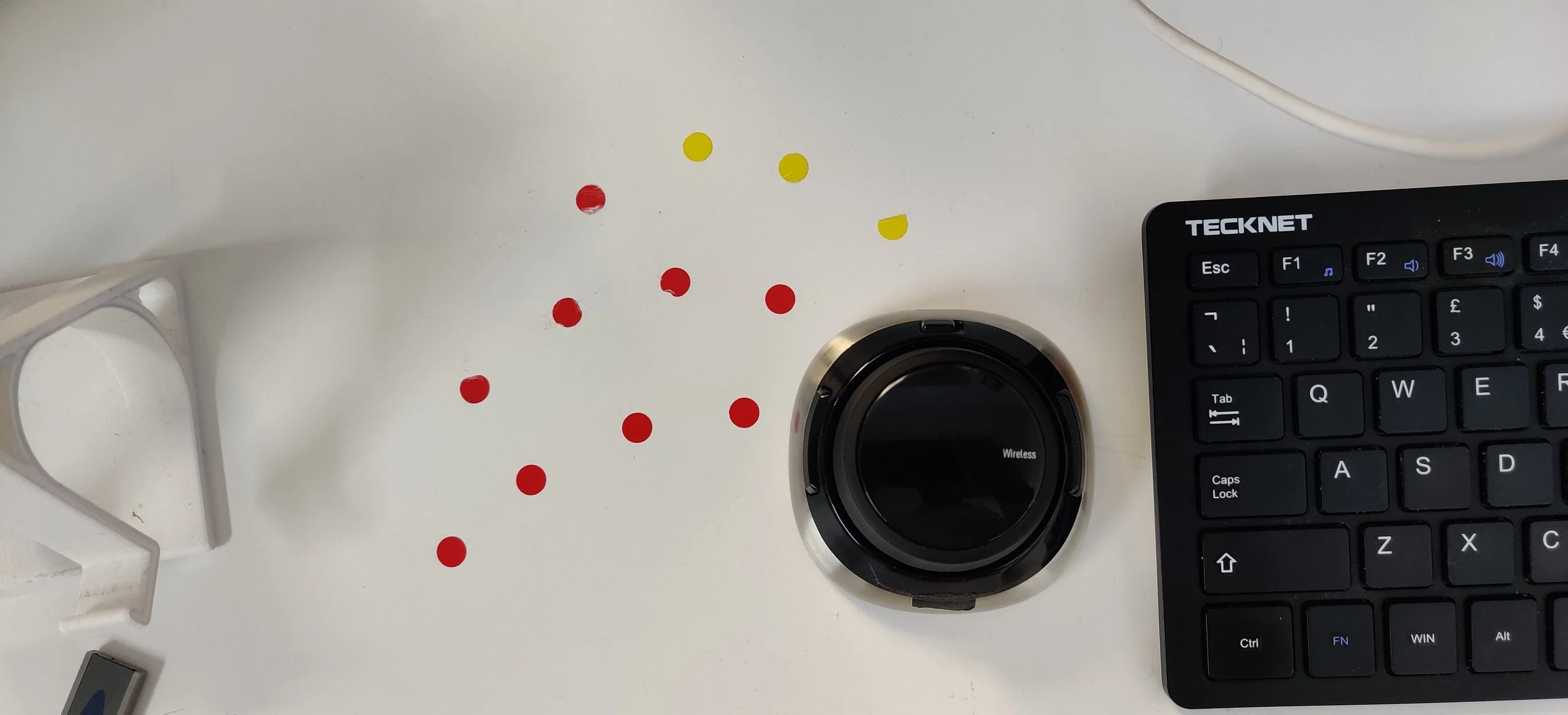
then I brought that into Solidworks to use it as a reference image to do some component layout to see what a finished macro pad would look like


Followed by many iterations of laser-cut & 3D Printed layouts to make iterative improvements


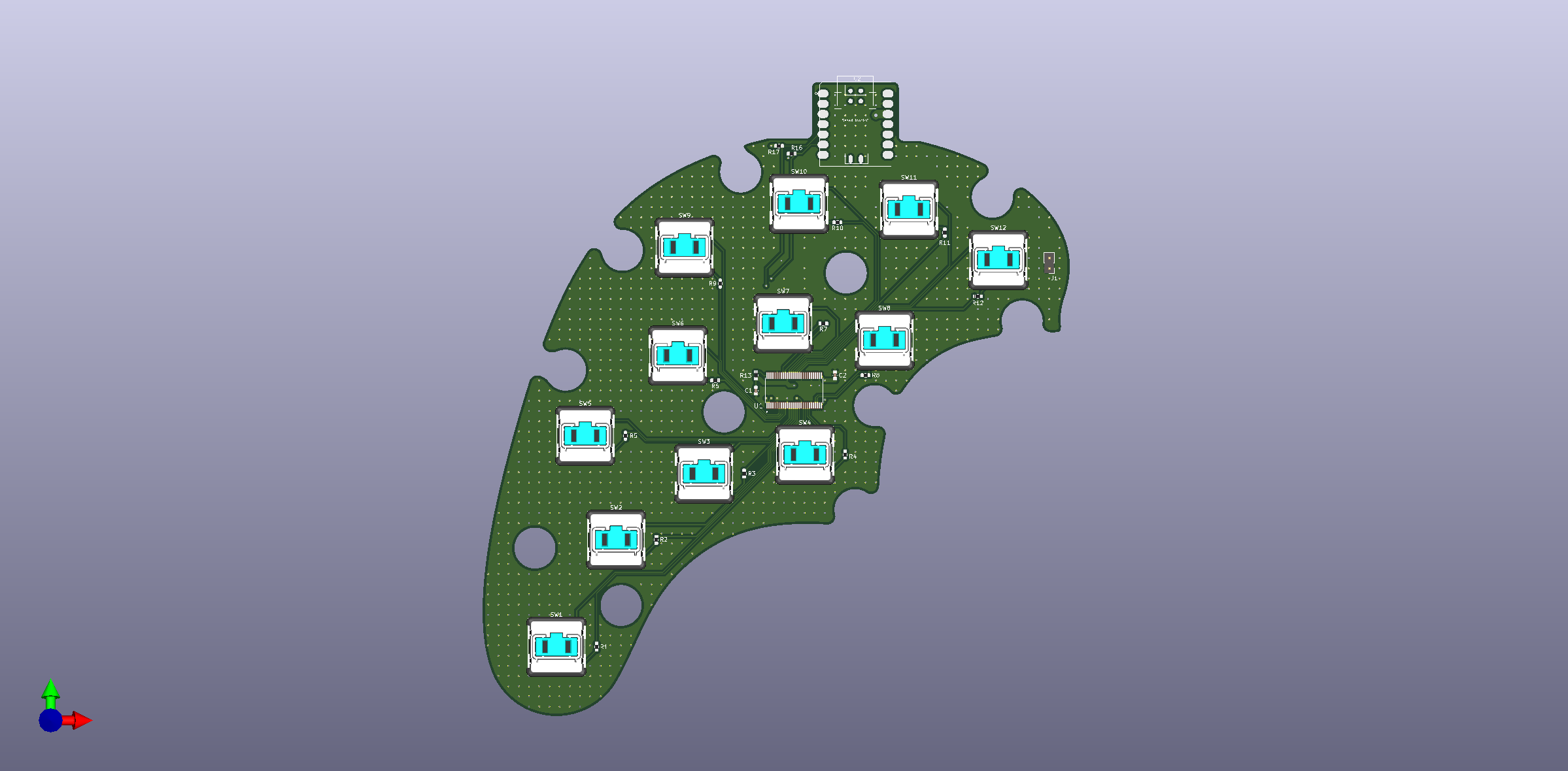
PCB design was severely limited by the current (2022) chip shortage. It was a fun challenge to design a PCB with heavy component selection constraints.


Completed Product

Here are some glamour shots of the finished item.


Future Work

  • Make the macro pad thinner by ~2mm

  • Replace the 3D Printed outer shell with a CNC machined and anodised part

  • Make power passthrough from Macro Pad to SpaceMouse


If you would like to build one ~> GitHub

6 Axis Robotic Arm

Motivation

I’ve been experimenting with ROS (Robotic Operating System) for a while and wanted a platform that I can use to further my knowledge. The BCN3D Moveo is a widely used open-source design for a 3D printable 5DOF robotic arm, and it costs about £500 to build. It is mechanically well-designed, though it lacks a platform for feedback control. Instead, it uses G-code. popular procedural instruction set used in 3D-Printing and CNC machining. Though it works well in predefined motion scenario, doesn't work well when comes to feedback control (i.e. using data from sensors on the robotic arm to make real-time decisions regarding movement). ROS based platform with robust feedback control will allow me to use external conditional triggering, use of IMU, force sensors, vision input and much more.


Design

Open source design of the BCN3D Moveo was a fantastic base to start from. I made the following changes.

  • Added a rotational axis to the wrist.

  • Made design changes to improve printability without using support material

  • Complete revamp of the stepper drivers to handle much bigger stepper motors

  • Changed the control platform from Arduino to Raspberry Pi

  • Minor mechanical improvement where I thought the cross sections were weak

Maheemal 6 axis arm render 1.jpg
Maheemal 6 axis arm render 2.jpg
 

3D Printing & Construction

 
Parts after sanding, and painting

Parts after sanding, and painting

 
During building

During building

 
Maheemal 6 axis arm near complete 1.jpeg
Maheemal 6 axis arm near complete 2.jpeg


All Completed


Preliminary ROS Integration


I started by creating a URDF (Unified Robotic Description File) of the Robot Arm using Solidworks. this details the configuration of the lings, how they are joined, and the physical constraints etc required in building a functional 3D rendering for the simulation in ROS packages such as RVIZ, and Gazebo. This was then used to configure the Arm with Moveit. This added motion planning capability to the Arm in simulation. using this setup, it is possible to plan and execute trajectories using a variety of motion planning algorithms. Here is an image of the simulation in action with motion planning.

Maheemal 6 axis arm ROS.png
 

Future Work

  • Incorporate Slip-Rings to route wires internally

  • Setup automatic homing (either with microswitches or absolute position encoders)

  • Missed-Step/Stall detection for the motors

  • Further improvements to the ROS Interrogation (move out of the limitations posed by ARM processor architecture)

  • Design a force sensing gripper

  • Adding additional sensors for the robotic arm, such as IMU, RGBD sensors, and force sensors.